The Sales Coaching Template For High-Performing Teams
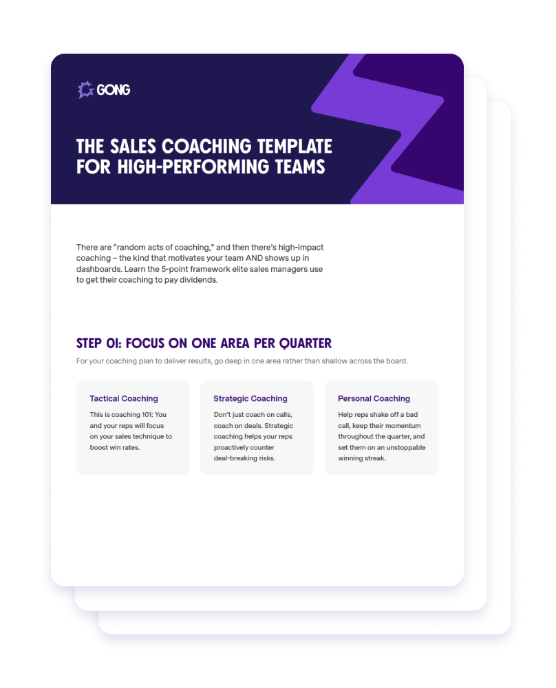
There are “random acts of coaching,” and then there’s high-impact coaching – the kind that motivates your team AND shows up in dashboards. Steal this template and use this 5-point framework elite sales managers use to get their coaching to pay dividends.
In this guide, you’ll discover:
- 3 straightforward coaching opportunities most leaders missThese surprisingly simple coaching opportunities will boost win rates, improve deal momentum, and set your reps on an unstoppable winning streak.
- The 5-point framework for high-performing teamsUse the coaching framework in this template to identify improvement opportunities, provide feedback, and drive real behavior change.
- How to spend less time, getting more doneThe problem with most coaching isn’t time. It’s how time is spent. Skip past common – and unproductive – coaching mistakes and reap the rewards of a winning process.
FAQs
What examples are included in the sales coaching template?
Light discovery. Poor objection handling. Low momentum. Account strategy. De-risking pipeline. Competitive deal playbook. No next steps. And more.
How much time will I need to dedicate to coaching for this template to work?
However much you are currently dedicating to coaching: This template comes with no additional time investment on your part, just more return on investment for the time you’re already spending on it by focusing your efforts and using data to guide your reps.
How do I know the sales coaching template works?
This template includes metrics to track based on your team’s key improvement areas. Build the plan, track the metrics, and watch your team’s results soar.
What makes Gong such experts on sales coaching?
First of all, we make some pretty terrific sales coaching software. Not to brag or anything, but Gong is the #1 on the list of Best Software Products for 2022 from G2 Crowd. But don’t take it from us: go check out the thousands of reviews from other sales professionals and you’ll see that we know a thing or two about sales coaching.
Do you have any other resources on how to improve sales coaching?
Yes, we most certainly do. Here’s a few nuggets from 3 Can’t-Miss Sales Coaching Opportunities:
- Three tactical coaching opportunities: sales call recordings; role play; and self-discovery
- How to coach on deals, including the opportunity that deal warnings present
- How reps can review their game tapes to self-improve
Need some more? Be sure to read our Guide To High-Performance Sales Coaching. There’s tons of good sales coaching tips in there, including a five-step coaching framework that you can use with your own teams.
Do you have any real-world examples or case studies of sale coaching in action?
We love showcasing how our customers have successfully used Gong to improve their sales coaching. You can learn how Zillow uses Gong to coach its reps in real time, for example. Or how Hubspot uses Gong for coaching its new hires. Across all of our customer stories, you’ll find practical tips that you can apply to your own day to day.
TALENT WINS DEALS. COACHING WINS CHAMPIONSHIPS.
Learn how top sales coaches level up their team with the sales coaching template.